Circuit Diagram Of Power Factor Correction Power Factor Corr
Power factor correction schematic diagram Factor power correction nist operation devices appears demystifies utility team Circuit factor power correction diagram inductive pfc ametherm using current capacitor thermistor ntc voltage source guidelines
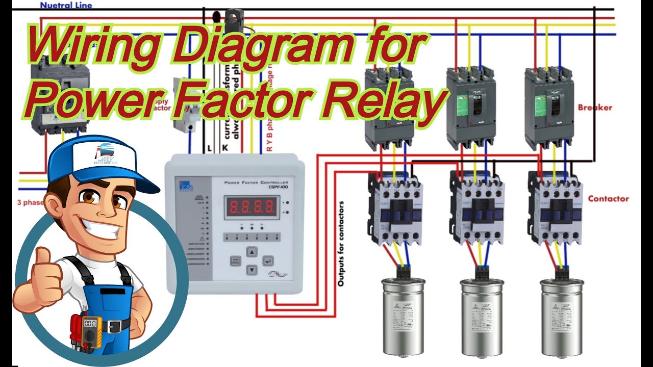
Complete Auto Power Factor Panel Wiring Diagram - YouTube
The circuit design of the introduced power factor correction (pfc Automatic power factor controller circuit diagram Power factor correction using capacitor bank
Automatic power factor correction using capacitor
Power factor correction circuit diagramInside the capacitor bank panel: power factor correction, calculation Power factor correction methodsCorrection capacitor phase circuit capacitors connected circuitglobe.
Power factor correction11+ power factor correction circuit diagram Power factor correction circuit patentsThe circuit diagram of the single-phase power factor correction system.

Power factor correction
Power factor correction circuit diagramPower factor correction Correction capacitor inductive reactive generator electricalacademiaCapacitor factor correction inductive pfc parallel thermistor ntc.
Automatic power factor controller circuit using microcontrollerBlock diagram of power factor corrector circuit. Power factor correction in operation.Diagram circuit factor correction power i0 source.

Complete auto power factor panel wiring diagram
Introduction to power factor correction pfc capacitors and circuitsActive power factor correction circuit diagram Automatic power factor correction using arduino electrosalFactor microcontroller automatic correction microcontrollerslab.
Factor power correction circuit simulatorDesigning a power factor correction circuit 11+ power factor correction circuit diagramPower factor correction topologies.

Factor correction power circuit capacitor formula electrical confused electronics
Power factor explainedWhat is power factor correction? Patent ep1944856a1Power factor correction.
Factor power correction circuitPower active circuit correction supply pfc factor basics basic Active power factor correctionPfi panel wiring diagram.

Pfc circuit diagram
Factor correction sustainability distributed improvingPower supply design basics: active power factor correction Factor correction poor explained correcting mindsetDesign guidelines for a power factor correction (pfc) circuit using a.
.


